
PTFE-Lined Hand-Wrapped Rubber Expansion Joint
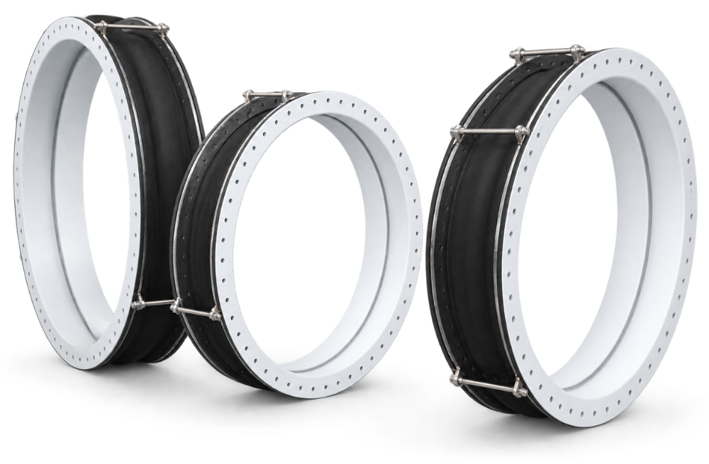
A PTFE-Lined Hand-Wrapped Rubber Expansion Joint is a specialized flexible piping component designed for industrial systems that require a combination of chemical resistance, vibration isolation, and movement accommodation. It combines a polytetrafluoroethylene (PTFE) inner liner with a hand-wrapped rubber body and suitable end connections to meet demanding process piping requirements.
Unlike conventional rubber expansion joints, this design incorporates a PTFE lining to provide a chemically resistant contact surface for compatible process media. The hand-wrapped manufacturing process is particularly useful for certain large-diameter or non-standard configurations where customized construction may be required.
How Does the Product Work?
A PTFE-lined hand-wrapped rubber expansion joint forms a flexible connection between adjacent sections of piping or between equipment and piping. Its flexible rubber body can accommodate specified axial, lateral, and angular movements, depending on the design. It can also help reduce the transmission of mechanical vibration and structure-borne noise through connected pipework.
The PTFE liner provides a barrier between the conveyed medium and the underlying rubber construction. This arrangement can be beneficial when the process medium is chemically aggressive or when the exposed rubber surface would not provide adequate compatibility.
The actual performance depends on the complete assembly, including the liner, rubber compound, reinforcement, flange design, operating conditions, and installation arrangement.
A standard rubber expansion joint exposes its selected rubber compound to the conveyed medium, whereas a PTFE-lined design provides a PTFE contact surface. This can improve chemical compatibility for applications in which the medium is unsuitable for direct contact with the rubber compound. However, the liner does not eliminate the need to evaluate the backing rubber, reinforcement, flanges, and seals. The appropriate design depends on chemical concentration, temperature, pressure, movement, and other operating conditions.
PTFE is resistant to many acids, alkalis, and industrial chemicals, making it a potential choice for chemical transfer and process piping applications. Nevertheless, no universal compatibility statement can guarantee suitability for every chemical mixture or operating condition. Concentration, temperature, impurities, exposure duration, and permeation requirements must be considered. Customers should provide the exact chemical name, concentration, operating temperature, and design pressure so that the liner and complete joint construction can be evaluated.
Vacuum service may be possible when the expansion joint is specifically designed and manufactured for the required negative pressure. The suitability depends on the joint diameter, length, rubber construction, reinforcement, liner arrangement, and operating temperature. Internal support rings or other anti-collapse features may be necessary in certain applications. Buyers should specify the required vacuum level and whether it is continuous or intermittent. A standard positive-pressure design should never be assumed suitable for full-vacuum service without engineering confirmation.
Selection starts with the nominal pipe diameter, required face-to-face length, flange drilling, operating pressure, design pressure, and temperature range. Engineers must also evaluate axial, lateral, and angular movements, the conveyed medium, and any pressure fluctuations or vacuum conditions. The expansion joint’s allowable movements and pressure rating must be verified for the selected configuration. Accurate piping drawings and mating-flange details help prevent dimensional mismatches and reduce installation problems.
A flexible rubber expansion joint can help reduce the transmission of vibration and structure-borne noise between connected equipment and piping. It may be considered for centrifugal pumps, chemical dosing pumps, process circulation pumps, and other compatible systems. Its effectiveness depends on the vibration frequency, joint stiffness, piping layout, equipment operating conditions, and installation quality. It does not replace a properly designed vibration isolation system, and unsuitable pipe supports or excessive pressure thrust can compromise performance.
The joint should be installed according to its approved drawing and the manufacturer’s instructions. Confirm flange alignment, face-to-face dimensions, gasket requirements, bolt tightening procedures, and flow direction if specified. Avoid twisting the joint, forcing it into position, or using it to compensate for excessive misalignment. Provide appropriate pipe supports, guides, anchors, and pressure-thrust restraints where required. The installation must also remain within the specified movement limits and account for thermal expansion and operating loads.
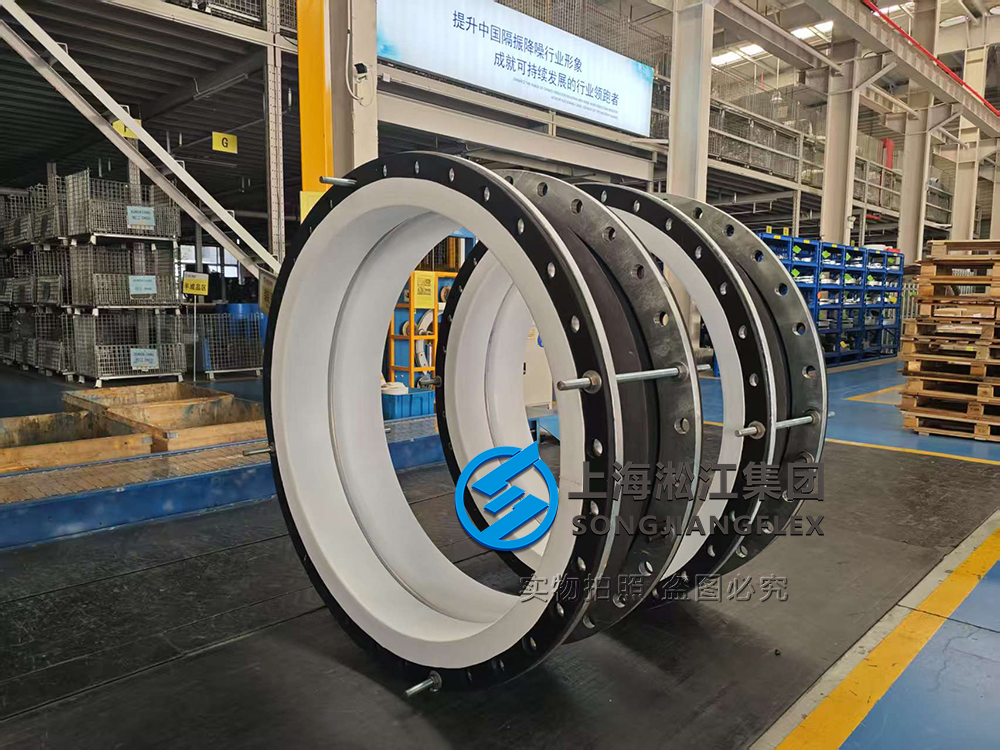
Customization may be available for selected large diameters, face-to-face lengths, flange materials, rubber compounds, liner configurations, reinforcement arrangements, and movement requirements. Manufacturing feasibility depends on the required dimensions, pressure and vacuum conditions, process medium, and construction details. For an accurate technical review, provide a dimensioned drawing, piping specifications, chemical information, operating conditions, and required quantity. Any special requirements, such as full-vacuum resistance, unusual flange standards, or non-standard liner thickness, should be identified before quotation.
What Are the Main Technical Benefits?
Chemical resistance: The PTFE contact surface can help protect the underlying rubber construction when the process medium is compatible with PTFE.
Vibration isolation: The flexible rubber body can reduce the transmission of vibration from pumps, motors, compressors, and other rotating equipment.
Movement accommodation: The joint can accommodate specified piping movements caused by thermal expansion, equipment displacement, and installation tolerances.
Customized construction: Hand-wrapped manufacturing can support selected large-diameter and non-standard designs, subject to manufacturing feasibility.
Reduced piping stress: When correctly selected and installed, the joint can help accommodate movement and reduce unwanted loads associated with piping misalignment.
It is important to distinguish flexibility from structural support. A rubber expansion joint is not automatically a substitute for pipe anchors, guides, thrust restraints, or dedicated pressure-bearing supports. The complete piping system must be assessed to ensure safe operation.
WCR-PTFE Type Hand-Wrapped Rubber Expansion Joint – Technical Data
Nominal Diameter (DN) (mm) | Size (in) | Standard Length (mm) | Available Length (mm) | Axial Extension (mm) | Axial Compression (mm) | Lateral Movement (mm) | Angular Movement (°) | Standard Pressure (bar) | Maximum Pressure (bar) |
|---|---|---|---|---|---|---|---|---|---|
WCR-50 | 2″ | 150 | 150–500 | 10 | 20 | 10 | 10 | 10 | 80 |
WCR-65 | 2½” | 200 | 150–500 | 10 | 20 | 20 | 10 | 10 | 80 |
WCR-80 | 3″ | 200 | 150–500 | 10 | 20 | 20 | 10 | 10 | 80 |
WCR-100 | 4″ | 200 | 150–500 | 10 | 25 | 20 | 10 | 10 | 80 |
WCR-125 | 5″ | 200 | 150–500 | 10 | 25 | 20 | 10 | 10 | 50 |
WCR-150 | 6″ | 200 | 150–500 | 10 | 25 | 20 | 10 | 10 | 50 |
WCR-175 | 7″ | 200 | 150–500 | 15 | 25 | 20 | 10 | 10 | 50 |
WCR-200 | 8″ | 200 | 150–500 | 15 | 25 | 20 | 10 | 10 | 50 |
WCR-225 | 9″ | 200 | 200–500 | 15 | 25 | 20 | 10 | 10 | 50 |
WCR-250 | 10″ | 200 | 200–500 | 15 | 25 | 20 | 8 | 10 | 40 |
WCR-300 | 12″ | 200 | 200–500 | 15 | 25 | 20 | 8 | 10 | 40 |
WCR-350 | 14″ | 250 | 200–500 | 15 | 30 | 25 | 5 | 10 | 40 |
WCR-400 | 16″ | 250 | 200–500 | 15 | 30 | 25 | 8 | 10 | 40 |
WCR-450 | 18″ | 250 | 200–500 | 30 | 30 | 25 | 8 | 10 | 40 |
WCR-500 | 20″ | 250 | 200–500 | 30 | 30 | 25 | 7 | 10 | 40 |
WCR-550 | 22″ | 250 | 200–500 | 30 | 30 | 25 | 7 | 10 | 40 |
WCR-600 | 24″ | 250 | 200–500 | 30 | 30 | 25 | 5 | 10 | 40 |
WCR-650 | 26″ | 250 | 200–500 | 30 | 30 | 25 | 5 | 10 | 40 |
WCR-700 | 28″ | 250 | 200–500 | 30 | 30 | 25 | 4 | 10 | 40 |
WCR-750 | 30″ | 250 | 200–500 | 30 | 30 | 25 | 4 | 10 | 40 |
Nominal Diameter (DN) (mm) | Size (in) | Standard Length (mm) | Available Length (mm) | Axial Extension (mm) | Axial Compression (mm) | Lateral Movement (mm) | Angular Movement (°) | Standard Pressure (bar) | Maximum Pressure (bar) |
|---|---|---|---|---|---|---|---|---|---|
WCR-800 | 32″ | 300 | 250–500 | 30 | 30 | 25 | 4 | 10 | 40 |
WCR-850 | 34″ | 300 | 250–500 | 30 | 30 | 25 | 4 | 10 | 40 |
WCR-900 | 36″ | 300 | 250–500 | 30 | 30 | 25 | 3 | 10 | 40 |
WCR-1000 | 40″ | 300 | 250–500 | 30 | 30 | 25 | 3 | 10 | 40 |
WCR-1050 | 42″ | 350 | 250–500 | 30 | 35 | 25 | 3 | 10 | 20 |
WCR-1100 | 44″ | 350 | 250–500 | 30 | 35 | 25 | 3 | 10 | 20 |
WCR-1150 | 46″ | 350 | 250–500 | 30 | 35 | 25 | 3 | 10 | 20 |
WCR-1200 | 48″ | 350 | 250–500 | 30 | 35 | 25 | 2.5 | 10 | 20 |
WCR-1250 | 50″ | 350 | 250–500 | 30 | 35 | 25 | 2.5 | 10 | 20 |
WCR-1300 | 52″ | 350 | 250–500 | 30 | 35 | 25 | 2.5 | 10 | 20 |
WCR-1350 | 54″ | 350 | 250–500 | 30 | 35 | 25 | 2.5 | 10 | 20 |
WCR-1400 | 56″ | 350 | 250–500 | 30 | 35 | 25 | 2 | 10 | 20 |
WCR-1500 | 60″ | 350 | 250–500 | 30 | 35 | 25 | 2 | 10 | 20 |
WCR-1600 | 64″ | 350 | 250–500 | 30 | 35 | 25 | 2 | 10 | 20 |
WCR-1700 | 68″ | 350 | 250–500 | 30 | 35 | 25 | 1.5 | 10 | 20 |
WCR-1800 | 72″ | 350 | 250–500 | 30 | 35 | 25 | 1.5 | 6 | 20 |
WCR-1900 | 76″ | 350 | 250–500 | 30 | 35 | 25 | 1.3 | 6 | 20 |
WCR-2000 | 80″ | 350 | 250–500 | 30 | 35 | 25 | 1.3 | 6 | 20 |
WCR-2100 | 84″ | 350 | 250–500 | 30 | 35 | 25 | 1.2 | 6 | 20 |
WCR-2200 | 88″ | 350 | 250–500 | 30 | 35 | 25 | 1.2 | 6 | 20 |
WCR-2300 | 92″ | 350 | 250–500 | 30 | 35 | 25 | 1 | 6 | 20 |
WCR-2400 | 96″ | 350 | 250–500 | 30 | 35 | 25 | 1 | 6 | 20 |
WCR-2500 | 100″ | 350 | 250–500 | 30 | 35 | 25 | 0.8 | 4 | 20 |
WCR-2600 | 104″ | 350 | 250–500 | 30 | 35 | 25 | 0.8 | 4 | 20 |
WCR-2800 | 112″ | 350 | 250–500 | 30 | 35 | 25 | 0.7 | 4 | 20 |
WCR-3000 | 120″ | 350 | 250–500 | 30 | 35 | 25 | 0.7 | 4 | 20 |
WCR-3200 | 128″ | 350 | 250–500 | 25 | 30 | 20 | 0.6 | 4 | 20 |
WCR-3400 | 136″ | 350 | 250–500 | 25 | 30 | 20 | 0.6 | 4 | 20 |
WCR-3500 | 140″ | 350 | 250–500 | 25 | 30 | 20 | 0.5 | 4 | 20 |
WCR-3600 | 144″ | 350 | 250–500 | 25 | 30 | 20 | 0.5 | 4 | 16 |
WCR-3800 | 152″ | 350 | 250–500 | 25 | 30 | 20 | 0.4 | 4 | 16 |
WCR-4000 | 160″ | 350 | 250–500 | 25 | 30 | 20 | 0.4 | 4 | 16 |
If you are looking for an AMVB All-Metal Vibration Isolator, stainless steel shock mount, precision instrument vibration isolator, or multi-directional vibration isolation solution, please send us your equipment specifications and installation requirements.
Our company’s new website is now live, featuring the latest product introductions. For more details, please visit more products.
Or you can send your inquiry directly to [email protected].