
JF Bell Mounts – Marine Engine Vibration Isolators
JF Bell Mounts are compact, fail-safe rubber vibration isolators designed for marine engines, diesel generator sets, and a wide range of marine propulsion and auxiliary equipment. Engineered to reduce vibration transmission and structure-borne noise, these mounts help improve equipment stability, operating comfort, and overall system reliability.
Featuring a low-profile, space-saving design, JF Bell Mounts are easy to install in confined engine compartments and machinery spaces. Their rubber elements operate under a combination of shear and compression, providing effective vibration isolation while maintaining controlled stiffness in three directions.
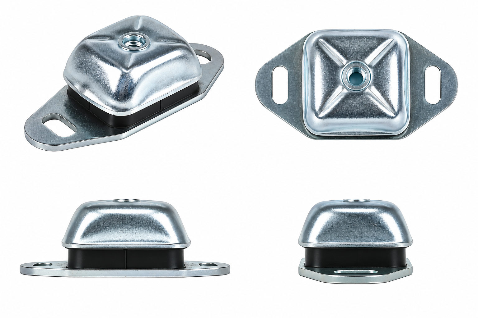
How Do JF Bell Mounts Provide Reliable Vibration Isolation?
JF Bell Mounts – Marine Engine Vibration Isolators are rubber-metal mounting components designed to reduce vibration transmission, control equipment movement, and provide stable support for marine propulsion engines, diesel generator sets, and auxiliary machinery.
These fail-safe marine engine mounts feature a compact, low-profile construction consisting of a formed metal housing, a rubber elastic element, and a slotted metal mounting base. The upper housing incorporates a central threaded connection for securing the supported equipment, while the base allows attachment to the supporting structure.
The rubber element operates through a combination of shear and compression deformation. This arrangement provides vertical flexibility for vibration isolation while maintaining directional stiffness to control longitudinal and lateral movement.
Key Structural Features and Technical Advantages
Compact Bell-Shaped Housing: Provides a low installation profile for machinery rooms and confined engine compartments.
Rubber-Metal Construction: Combines the load-bearing capability of metal components with the elastic deformation characteristics of rubber.
Three-Axis Vibration Control: Provides different stiffness characteristics in vertical, longitudinal, and lateral directions.
High Vertical Flexibility: Helps reduce vibration transmitted from rotating and reciprocating equipment into the supporting structure.
Fail-Safe Design: Incorporates mechanical restraint intended to limit excessive movement if the rubber element fails.
Slotted Mounting Holes: Allow limited positional adjustment during installation and equipment alignment.
Start by identifying the total equipment weight, number of mounting points, and center of gravity. Divide the equipment load according to the actual load distribution rather than assuming every mount carries an equal share.
Next, check the engine operating speed, vibration excitation frequencies, mounting orientation, and allowable deflection. Select a mount whose rated capacity accommodates the expected static load and operating conditions.
For marine propulsion engines, longitudinal thrust, torque reaction, and vessel movement should also be evaluated before confirming the mounting arrangement.
JF Bell Mounts use a rubber-metal construction consisting of a formed metal housing, an elastic rubber element, and a metal mounting base.
The metal components provide structural support and mechanical attachment, while the rubber element supplies flexibility and vibration isolation.
Different Shore A hardness grades are available to accommodate different loading requirements. However, the specific rubber compound, metal grade, and surface treatment should be confirmed against the selected product specification.
For marine environments, resistance to salt spray, oil exposure, temperature variation, and long-term rubber aging should be considered during material selection.
The maximum rated load depends on the mounting size and rubber hardness.
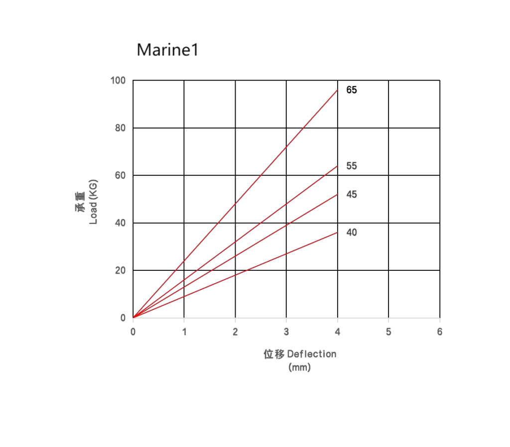
According to the available technical data, JF-60M12 models have maximum rated loads from 36 kg to 96 kg per mount, while JF-78M16 models range from 80 kg to 475 kg.
The larger JF-112M20 series provides maximum rated loads from 330 kg to 810 kg per mount.
These values represent specified load ratings, not automatically approved working loads for every installation. Dynamic forces, load distribution, allowable movement, and operating conditions must be considered when selecting the appropriate model.
JF Bell Mounts should be installed on a stable, sufficiently rigid supporting surface with the mounting holes correctly aligned.
The equipment load should be distributed according to the mounting arrangement, and each isolator should remain within its specified operating range.
Fasteners must be selected and tightened according to the applicable installation requirements. Avoid introducing unnecessary preload, twisting, or misalignment into the rubber element.
After installation, check the mount deflection, equipment alignment, and clearance around moving components. Flexible piping and suitable coupling arrangements may be required to maintain effective vibration isolation.
JF Bell Mounts can reduce structure-borne vibration and the associated noise transmitted through machinery foundations.
Their effectiveness depends on the relationship between the mount’s natural frequency and the excitation frequencies generated by the equipment.
For effective vibration isolation, the excitation frequency generally needs to be sufficiently higher than the mounting system’s natural frequency. Near resonance, vibration transmission may increase rather than decrease.
The mounts do not directly eliminate airborne engine noise. Overall acoustic performance also depends on machinery enclosures, exhaust systems, piping connections, foundation stiffness, and surrounding structural components.
Rubber hardness describes the resistance of the rubber material to localized indentation, commonly measured using the Shore A scale.
Mounting stiffness describes the relationship between applied force and resulting displacement. It depends on rubber hardness, geometry, bonded area, deformation mode, and structural design.
For example, JF-78M16 models are available in several hardness grades, with corresponding average load-deflection rates from 16 to 95 kgf/mm.
A harder rubber compound generally produces a stiffer mounting arrangement, but it does not automatically provide better vibration isolation. The correct stiffness must match the equipment’s operating conditions.
Customization requirements can be evaluated according to equipment dimensions, mounting configuration, loading conditions, and environmental exposure.
Potential considerations include rubber hardness selection, mounting-hole configuration, installation height, metal surface treatment, and required directional stiffness.
Customers should provide equipment weight, center-of-gravity information, mounting-point positions, operating speed, and available installation space.
For marine engines, additional information about thrust forces, torque reaction, and allowable movement is particularly valuable.
Any proposed modification should undergo technical review to confirm that the revised construction remains suitable for the required loading and vibration isolation conditions.
JF Bell Mounts – Marine Engine Vibration Isolators – Technical Specifications
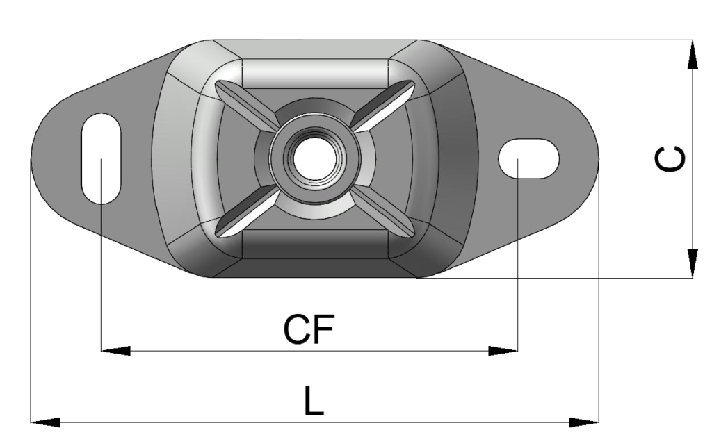
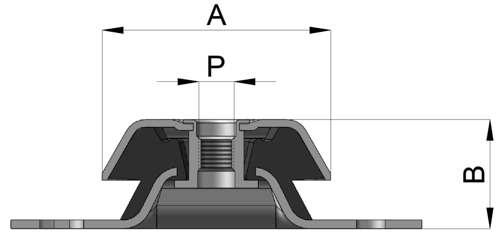
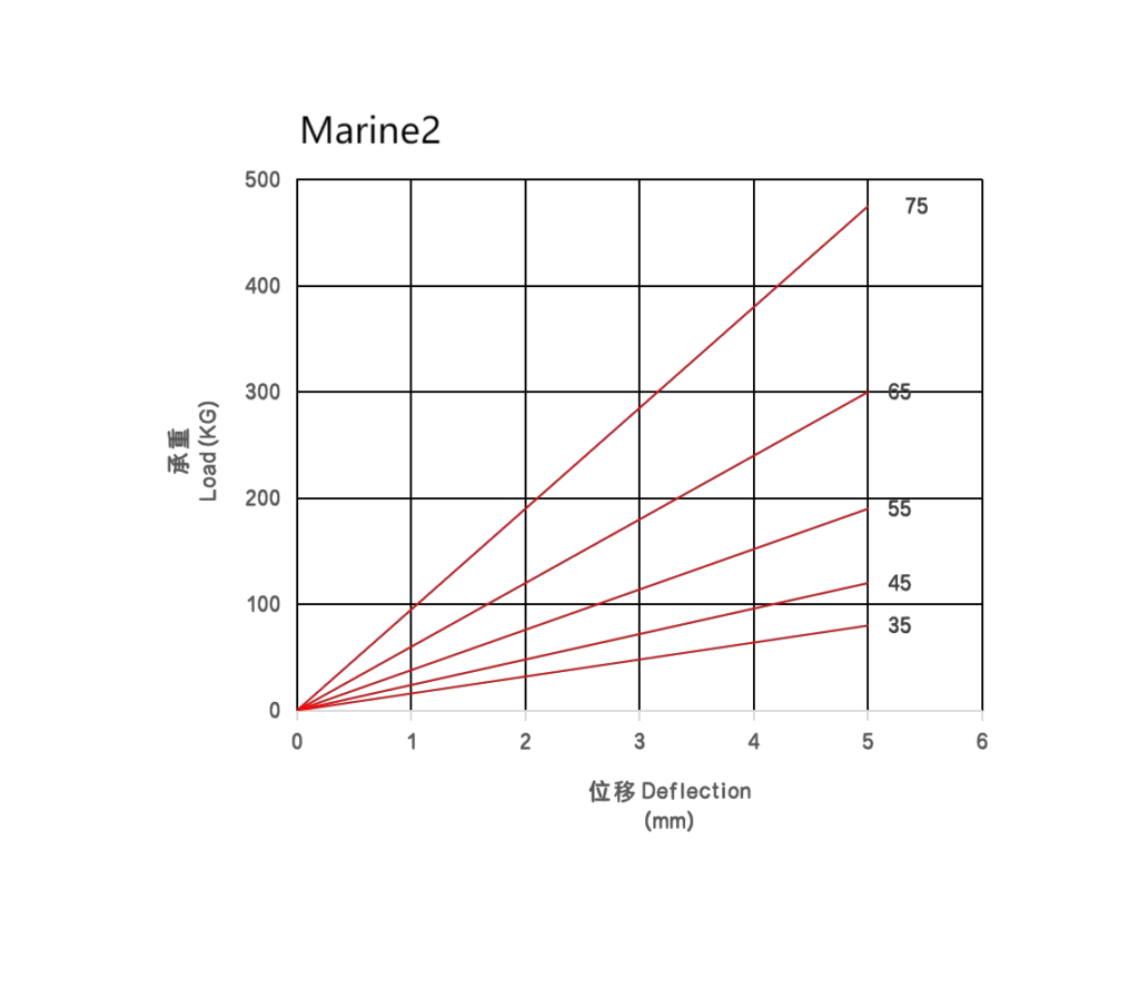
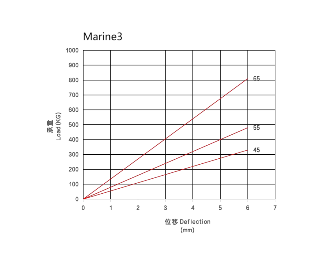
JF Bell Mounts – Technical Specifications
Model | Shore A Hardness | A (mm) | B (mm) | C (mm) | P | CF (mm) | L (mm) | Average Load (kg/mm) | Max. Load (kg) | Deflection (mm) |
|---|---|---|---|---|---|---|---|---|---|---|
JF-60M12 A40 | 40° | 80 | 38 | 60 | M12 | 100 | 120 | 9 | 36 | 4 |
JF-60M12 B45 | 45° | 80 | 38 | 60 | M12 | 100 | 120 | 13 | 52 | 4 |
JF-60M12 C55 | 55° | 80 | 38 | 60 | M12 | 100 | 120 | 16 | 64 | 4 |
JF-60M12 D65 | 65° | 80 | 38 | 60 | M12 | 100 | 120 | 24 | 96 | 4 |
JF-78M16 A35 | 35° | 104 | 50 | 78 | M16 | 140 | 186 | 16 | 80 | 5 |
JF-78M16 B45 | 45° | 104 | 50 | 78 | M16 | 140 | 186 | 24 | 120 | 5 |
JF-78M16 C55 | 55° | 104 | 50 | 78 | M16 | 140 | 186 | 38 | 190 | 5 |
JF-78M16 D65 | 65° | 104 | 50 | 78 | M16 | 140 | 186 | 60 | 300 | 5 |
JF-78M16 E75 | 75° | 104 | 50 | 78 | M16 | 140 | 186 | 95 | 475 | 5 |
JF-112M20 A45 | 45° | 132 | 71 | 112 | M20 | 182 | 230 | 55 | 330 | 6 |
JF-112M20 B55 | 55° | 132 | 71 | 112 | M20 | 182 | 230 | 80 | 480 | 6 |
JF-112M20 C65 | 65° | 132 | 71 | 112 | M20 | 182 | 230 | 135 | 810 | 6 |
Technical Notes:
Shore A Hardness: Rubber hardness measured on the Shore A scale.
A, B, C, CF, L: Mounting dimensions in millimeters.
P: Thread size.
Average Load: Load per millimeter of deflection (kg/mm).
Max. Load: Maximum rated load in kilograms.
Deflection: Rated vertical deflection under maximum load.
If you are looking for an AMVB All-Metal Vibration Isolator, stainless steel shock mount, precision instrument vibration isolator, or multi-directional vibration isolation solution, please send us your equipment specifications and installation requirements.
Our company’s new website is now live, featuring the latest product introductions. For more details, please visit more products.
Or you can send your inquiry directly to [email protected].